
Overcharge Protection
Last Updated: 3/6/19
To prevent the cells from charging past 4.2V/cell and achieving a dangerous energy level, I designed an overcharge protection circuit.
Overcharge Protection ✅


Overview
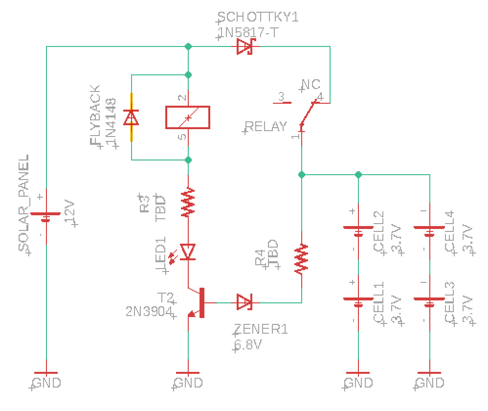
This circuit cuts off the the flow of charge from the solar panel to the batteries when the voltage drop across the cells reaches 8.4V. Each cell should not be charged above 4.2V, so with 2 in series, this adds up to 8.4V.
How It Works
Essentially, this circuit cuts off the charging half of the circuit by reverse biasing a Zener diode. The batteries charge when the relay is in its non-energized state, so to stop charging the cells, the relay must become energized when the voltage drop across the cells reaches 8.4V. To prevent the relay from energizing before then, the ground terminal is connected to the collector of a transistor whose base is connected to a Zener diode, a Schottky diode, and a resistor. When the batteries are below 8.4V, the voltage drop across the components in the base is insufficient to reverse bias the Zener, which prevents current flow and keeps the transistor in its non-conducting state (which acts as an open circuit to the relay). When the batteries reach 8.4V, though, base current flows which turns on the transistor, which allows current to flow through the relay, which opens the switch and disconnects the batteries. An LED then turns on to indicate that the batteries are fully charged.
Difficulties
The hardest part of this circuit was dealing with an unanticipated issue regarding the battery voltage reading. I naively assumed that the voltage drop across the batteries would only read the voltage level of the cells; however, I quickly discovered that essentially the entire 12V of the power supply was dropping across the batteries. Why? The internal resistance of the batteries was dropping all of the additional voltage between Vsupply and Vcells since there was no resistance between the charger and the cells. To fix this, I measured the internal resistance of the battery and placed resistors in series with the cells such that the voltage drop across the internal resistance of the battery would be negligible compared to the voltage drop across the resistors in series. This limits the power delivered to the cells, since the current going to them is now much lower.
At the end of testing when I went to change the value of the resistors in series, I discovered that my relay had stopped working for no apparent reason. I am currently investigating this issue and using a separate relay in the mean time.
Future Improvements
I think the largest opportunity for improvement here would be finding a way to measure the voltage drop across the cells without having to place resistors in series with them, which significantly limit the power delivered and charging speed.
Realistically thinking of the implementation of this in an EV or grid-scale battery pack, it seems like there are too many components to accomplish what seems like a simple task. There must be some alternate circuit to reduce the number of components and space required.
Last updated 3/6/19